|
|
MyPlasmaCutting.com By Fred Nelson Fabrication |
|
|
|
Land Rover Range Rover P38 Roof Rack Assembly Guide TOOLS NEEDED You should be able to install the entire P38 rack with a single 7/16ths combination wrench and possibly a small screwdriver to help line up brackets and bolt holes. A blanket or towel should be used to protect the roof during installation. PRE-ASSEMBLE THE MAIN RAILS. The FORWARD and REAR MAIN RAILS attach in the center and share a common 'foot' and side plate mounting bracket. The forward rails are flat at the front and the rear rails have an angle cut in them.
Line up the proper MAIN RAIL sections on the
ground.
Connect each MAIN RAIL together with
a RAIL CONNECTOR* *Don't over tighten. You can expect to loosen these up in order to properly line up and seat the CENTER CROSS BAR later.
Locate the 6 slide-open plastic
covers built in to the roof moldings.
Slide open the covers exposing the
steel channel under the molding* *push down at the arrow to slide open Take the appropriate steps to avoid scratching the roof during installation.
INSTALL THE MAIL RAILS Each MAIN RAIL has 3 "foot pads" that sit in the steel channel. Position them in the approximate center of the opening in the molding. The rails need to be positioned correctly front-to-rear to insure that the wind deflector fits properly against the roof above the windshield (later) and the rails clear the rear hatch when it is open.
The MAIN RAILS are installed with 3 brackets
facing outward.
The angled end points towards the rear. This and the rear cross bar need to clear the hatch. If the open hatch does not clear, slide the entire rack forward.
One RAIL CLIP will hold each foot in place. Loosely install the front and rear clips. The center clip needs to be installed at the same time as the CENTER CROSS BAR. Don't tighten anything too tight yet.
The RAIL CLIPS are installed on the outside of the rail with the 'foot' of the clip hooked under the lip of the steel channel. You may need to tilt the main rails inward in order to get the foot of each clip hooked under the lip on the channel before you can install or tighten any hardware.
There needs to be some weight on these 'feet' and the 3 MAIN CROSS BARS need to be installed in order for everything to line up, stiffen up, and begin to seat properly. The hardware for the center clip needs to be installed at the same time as the CENTER CROSS BAR. Check to insure the the rails do not interfere with the rear hatch. Loosely snug the hardware on the front and rear clips. Always push the 'feet' down into the steel channel to firmly seat them when installing or adjusting the clips and hardware. ABOUT THE CROSS BARS The front bar is #1, the center bar #7, and the rear bar #14. The roof of the P38 is not rectangular. It is wider at the front. Thus, the cross bars are different lengths.
The bars are
measured using the total length of the tube (the mounting tabs are
welded on each end 5/8 of an inch from the end). The chart below will serve as a guide. Lay the bars out on the
floor arranged from shortest to longest. Basically, the rear
bar is the shortest, the forward bar is one of the longest. The
center bar is distinctive and uses a wide mounting tab. Some of the bars are the same length.
INSTALL THE THREE MAIN CROSS BARS Begin by installing the 3 main cross bars starting with the center bar first then fill in the missing bars.
It may be necessary to loosen the top RAIL CONNECTOR in order to get everything to seat and settle correctly. Don't tighten everything too tight until there is some weight and tension on the entire assembly to insure everything settles down into the channels in the roof. Once you get a majority of the parts in place you can begin to snug up the hardware but don't over tighten. It may be necessary to make some movements and adjustments as you go along. Pay particular attention to insure the feet settle into the channel properly and the rail clips hook properly under the lip on the side of the steel channel. It may be necessary to push down on the assembly as you install the hardware for the center bar ends and center rail clips. It may also be helpful to install some hardware and tighten it in order to get things to line-up and seat, then loosen the hardware and re-snug once every thing is lined up. At this point the rack should begin to stiffen up and the center foot and clip should bite the channel lip firmly.
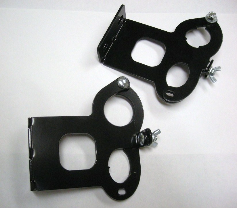
The first cross bar shares hardware with the front SIDE PLATE SUPPORT BRACKETS. The brackets look similar but are side specific. The driver's side bracket is the bracket on the right (photo below).
The forward brackets have a notch to clear the end of the first cross bar tube. Install the front (#1) cross bar and forward side plate supplemental brackets. Driver's side shown here (below).
INSTALL BARS #5 AND #8 Bars #5 and number #8 share hardware with the axe/shovel mount re-enforcement brackets. These brackets back-up the shovel mounts which will go on the out side of the driver's side SIDE PLATE (later). The forward bracket has more of an 'off-set' than the rear bracket. Forward bracket shown here on the left:
Install bar #5 and the forward shovel bracket (driver's side).
Install bar #8 and the rear shovel bracket (driver's side).
INSTALL THE REAR CROSS BAR The rear bar shares hardware with the rear SIDE PLATE SUPPORT BRACKETS. These brackets look similar but are different and side specific. The drivers side bracket shown here on the left, passenger side shown on the right (below).
INSTALL THE REMAINING CROSS BARS If you need complete sun roof access, omit the cross bars over the sun roof (leave bar #1 in place). Be advised, if you leave all bars in place, bar #4 may interfere slightly with the pop-up function of the sunroof at the full up position. You can still use this function with the bar in place, however, take care not to pop-up the sunroof to the point where it touches the cross bar.
INSTALL THE SIDE PLATES Take precautions not to scratch the vehicle. Install the forward side plates and some of the hardware. Do not install the shovel brackets yet. Do not tighten the hardware yet.
Install the hardware loosely until all hardware is in place then go back and tighten all the hardware once everything is lined up properly. It may even be necessary to go back and loosen some of the hardware you have already installed so you can make the proper adjustments to get all the mounting holes to line up correctly.
Install the remaining hardware.
There should be about 1/2 inch gap between the roof and the side plates.
The side plate mounting brackets (as with all of the other brackets) can be bent if needed to get the hardware to line up.
WIND DEFLECTOR INSTALLATION
P38 WIND DEFLECTOR BRACKETS NOTE: The entire rack may need to move forward or rearward slightly for the wind deflector to fit correctly. The deflector should have a slight forward 'bow'. The 4 small tabs that mount the deflector can be (gently) bent a little forward if needed to force the deflector to bow forward. INSTALL THE BOTTOM TRIM
Install the rubber bottom trim on the wind deflector then install the deflector hardware, loosely at first..
The deflector has a rubber trim on the bottom to protect the roof.
There should be a slight forward 'bow' in the deflector and it should sit against the roof just above the windshield. Attached one side, then push on the opposite side to create a forward bow then tighten the hardware. INSTALL THE AXE/SHOVEL MOUNTS (optional) Install the shovel and axe mount (driver's side). The brackets are different. The forward bracket has a larger opening for the head end of the shovel. Install as shown.
FORWARD MOUNT
REAR MOUNT
COMPLETED INSTALLATION
CHECK REAR CLEARANCE Make sure the rear of the rack clears the open rear hatch. Go back and re-tighten all the hardware and check again after the first few uses as some settling may occur. SPREAD OUT THE WEIGHT The rack has a capacity of several hundred pounds, but, you need to spread out the load. Place weight towards the outside of the rack rather than right in the center when possible. If you walk or stand on the rack, stand towards the outside, not right in the center. Use a piece of plywood under heavy loads to help evenly distribute the weight. If you do bend a bar, you can remove it, stand on it to bend it back into shape, then reinstall it. SUNROOF If you leave all of the bars in, be careful when you pop-up the sun roof so as not to hit cross bar #4. REPLACEMENT PARTS All parts for our Land Rover P38 Range Rover roof rack are available separately. Contact us if you need any replacement parts. All hardware is common and should be available locally. Thanks for your purchase and enjoy! Land Rover Range Rover P38 Roof Rack Assembly Guide
|
.JPG)
.JPG)
.JPG)

.JPG)
.JPG)

.JPG)
.JPG)

.JPG)
.JPG)


.JPG)
.JPG)
.JPG)
.JPG)


.JPG)
.JPG)
.JPG)

.JPG)
.JPG)

 3
3


QUESTIONS? Contact us
CONTACT US PHOTO GALLERY ONLINE STORE PLASMA CUTTING CUSTOMER SUBMITTED PHOTOS ENGRAVER DXF CNC CUTTING FILES
Fred Nelson Fabrication. Azusa, CA 1999-2012 All Rights Reserved